|
PCBA Capability
DIY PCBA
Quality Control
PCBA products
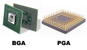
BGA
Lead-free PCBA
|
PCB assembly service
- we offer quick turn service for production PCB assembly
- we keep you updated on the status while doing assembly by sending you the photos
- Our PCB assembly quality control :
- X-Ray Inspection for BGA Assembly
- Components Quality control
- Assembly Quality Control
- Ultrasonic PCB cleaning
PCB Assembly Capacity
|
|
Item
|
Capacity
|
|
1
|
Single and double sided SMT/PTH
|
yes
|
|
2
|
Large parts on both sides, BGA on both sides
|
yes
|
| 3 |
Smallest Chips size
|
0201
|
|
4
|
Min BGA and Micro BGA pitch and ball counts
|
0.008 in. (0.2mm) pitch, ball count greater than 1000
|
|
5
|
Min Leaded parts pitch
|
0.008 in. (0.2 mm)
|
|
6
|
Max Parts size assembly by machine
|
2.2 in. x 2.2 in. x 0.6 in.
|
|
7
|
Assembly surface mount connectors
|
yes
|
|
8
|
Odd form parts:
LED
Resistor and capacitor networks
Electrolytic capacitors
Variable resistors and capacitors (pots)
Sockets
|
yes
|
|
9
|
Wave soldering
|
yes
|
|
10
|
Max PCB size
|
14.5 in. x 19.5 in.
|
|
11
|
Min PCB Thickness
|
0.02
|
|
12
|
Fiducial Marks
|
Preferred but not required
|
|
13
|
PCB Finish:
|
1.SMOBC/HASL
2.Electrolytic gold
3.Electroless gold
4.Electroless silver
5.Immersion gold
6.Immersion tin
7.OSP
|
|
14
|
PCB Shape
|
Any
|
|
15
|
Panelized PCB
|
1.Tab routed
2.Breakaway tabs
3.V-Scored
4.Routed+ V scored
|
|
16
|
Inspection
|
1.X-ray analysis
2.Microscope to 20X
|
|
17
|
Rework
|
1.BGA removal and replacement station
2.SMT IR rework station
3.Thru-hole rework station
|
Lead-time
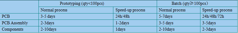 Note : The turnaroundr is guarantteed when we confirm all the parts in the warehouse . Some rare parts are not in the warehouse will delay the delivery time .
Get Quotation and place order
Contact us if you are ready to place order .You can send us your gerber file and BOM to sales@smiery.com for quotation , we will reply to you as soon as possible .The quotation list includes components fee , assembly fee , and stencil fee according to your BOM .If you can provide components and stencil ,or either one , that is acceptable .
Custom Products
The items below are examples of custom products we have made in the past. These items are normally not stocked, but can be requested. Requests are also taken for new or custom designs not listed on the products page. If you would like to request a product, please e-mail me at diy@smiery.com .
 |
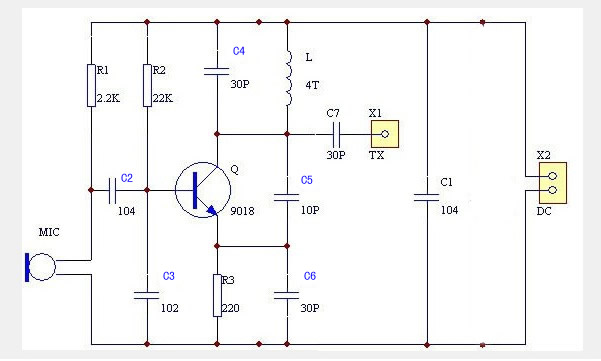 |
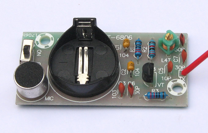
Frequency modulation wireless microphone , Radio transmitter module .
The transmission frequency is about 900hz .working voltage: DC 3V-6V, firing distance is about ten to tens meters, firing away with the power supply voltage, the antenna length and impedance matching, geographic extent open, electromagnetic interference, the receiver sensitivity related equipment. |
 |
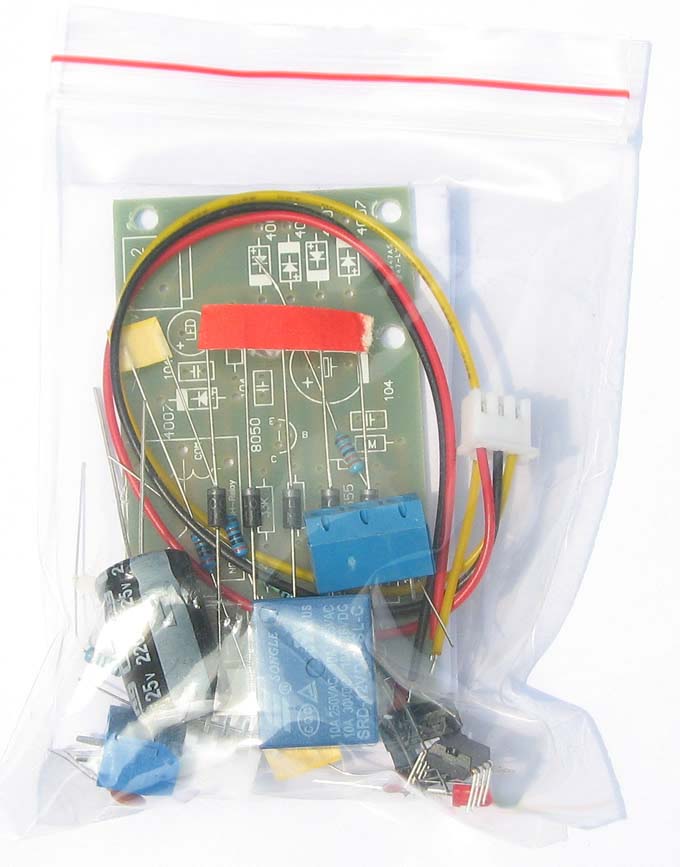 |
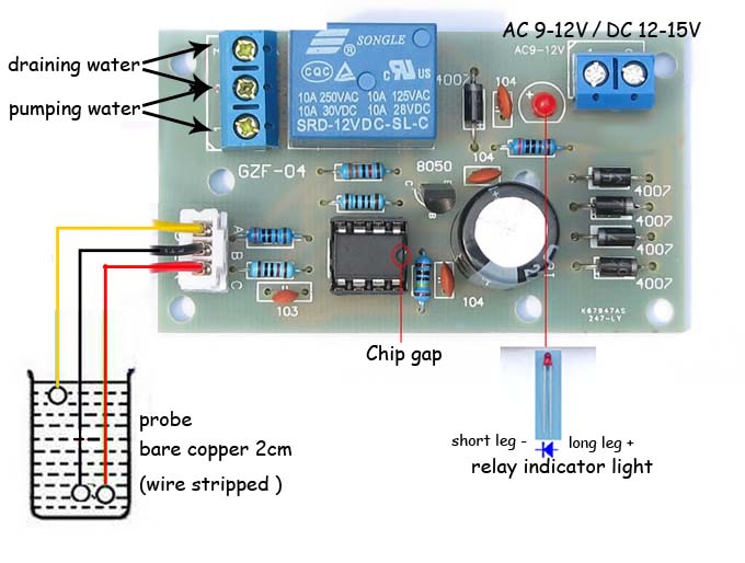
The product is based on the detection of the pool (warer tower) to control the water lever to achieve high current relay controlling the water pumping and rasing .With a small , simple wiring , low power , high switch capacity , strong anti-intererence function and high stability . Automatically open when can stably pool (water tower )water ,pumps pumping , the pump automatically stops when full of water .
Local flooding can also be used for automatic rain drainage , such as garages ,basements ,etc . |
 |
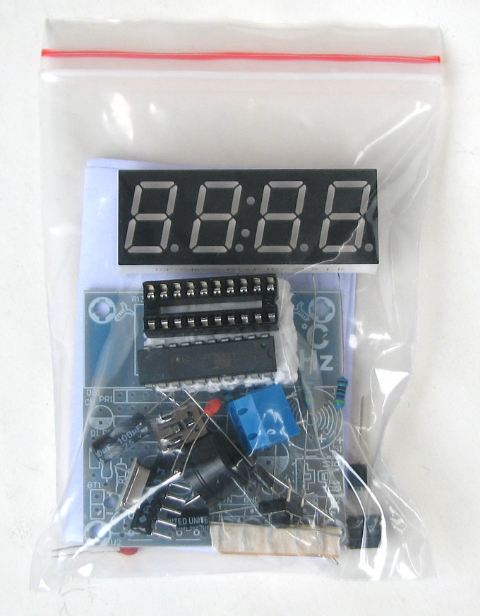 |
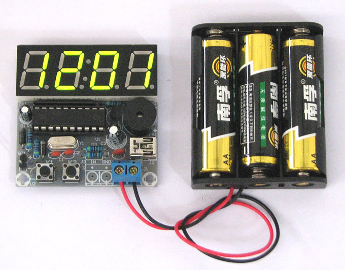
Multifunction 4 microcontroller gigital clock
Chip has been programmed
1,Normal travel-time
2,Sub independently adjustable
3,Two-way alarm , independently set ON/OFF
4,The countdown fuction can be acheived within 99 minuts
5,Counter function can be acheived , such as keystrokes , number of external pulses . |
 |
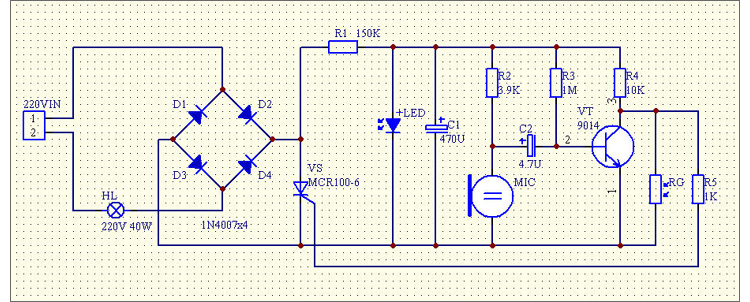 |
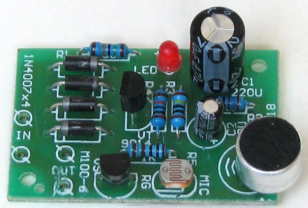
The light is off during day time . Sound makes the light on on the night . Then the light turns off automatically after a period delay .Conserve electricity , convenient controller |
 |
The design is based STC89C51 / 52 (with AT89S51 / 52, AT89C51 / 52 GM, optionally) and smallest single-chip microcontroller systems and pyroelectric (human infrared sensor), remote control (2272,2262), display and other components of the wireless alarm systems, the use of human body sensing module sensing, buzzer! |
Can set multiple (taking into account the cost of this kit only set all the way), you can have different alarm mode, such as vibration, sound, smoke, wind and rain, temperature and humidity, etc. (The design for the human infrared sensor alarm). |
 |
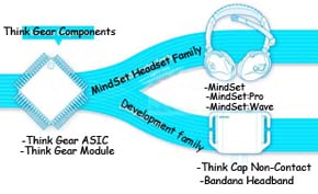 |
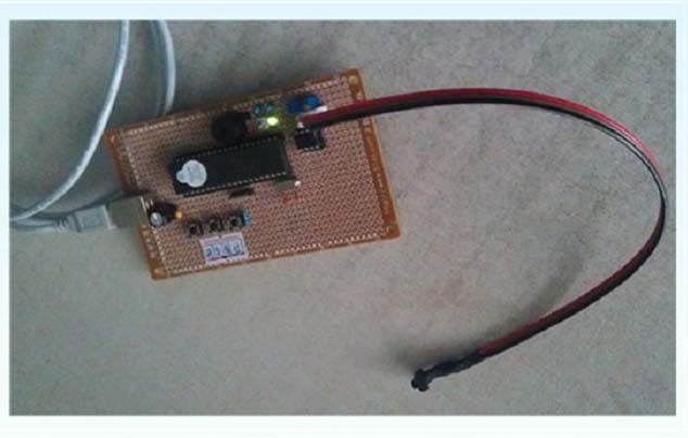
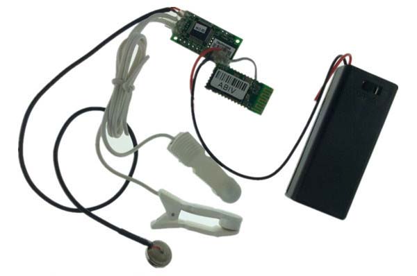
Brainwave instrument ,EEG biosensors :TGAM . The TGAM processes and outputs EEG frequency spectrums, EEG signal quality , raw EEG .EEG biosensors deliver the intelligence that enables hundreds of health and wellness, education and entertainment products.This is DIY Module Development Kit , using TGAM . |
 |
 |
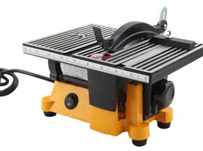
DIY machine , v-cut PCB easily !! |
 |
 |
Undercarriage sequencer / Aviation simulation Electronics / DIY |
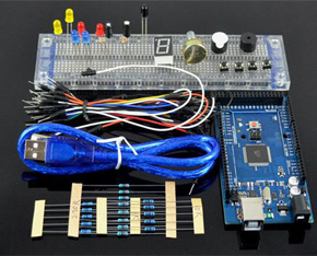 |
Kit list:
1 box * 1 2 development board * 1
3 MYB-120 Breadboard * 1
4 red, blue, yellow. LED light * 5
5 Resistance 220 Ohms * 8, 1K * 5, 10K * 5.
6 color jumper * 30
7.USB cable * 1 8 potentiometer * 1
9 digital tube * 1 10 active buzzer * 1
11 Passive Buzzer * 1 12 Key switch * 4
13 photoresistor * 2 14 tilt switch * 2
15 flame sensor * 1 16 packing boxes * 1 |
DIY basic kit -02 is the launch of a new interactive technology-based MEGA 2560 R3 development board tool box, which is equipped withcontroller board experimental basic materials, such as bread plate, bread lines, LED lights, resistors. Is an economical, portable learning tool for Arduino. |
(1).jpg) |
Electronic enthusiasts favorite DIY Android control wireless caterpillar smart car kit |
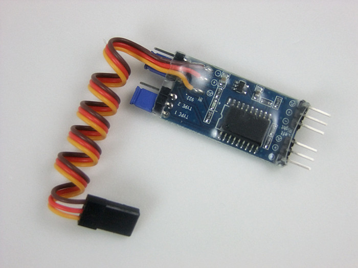
As long as the input signal end of a50HZ square wave signals, and then the cycle of the control signal of high level pulse duration can control the speed and reverse and stop. A high pulse duration corresponding to a speed. The high level of 1 ms ~1.5 MS, the steering gear is rotating (1 ms when the forward rate is the rapiddest, closer to1.5 ms slower,1.5 ms when the steering stop ), a high level of 1.5 ms ~2 MS rudder reversal (1.5 ms when the steering gear stops rotating, the more close to 2 MS inversion faster,2 ms to the fastest speed inversion ). |
X-Ray Inspection for BGA Assembly
The automated X-ray inspection systems are able to monitor a variety of aspects of a printed circuit board in assembly production. The inspection is done after the soldering process to monitor defects in soldering quality. The equipment is able to "see" solder joints that are under packages such as BGAs, CSPs and FLIP chips where the solder joints are hidden. This allows to verify that the assembly is done right. The defects and other information detected by the inspection system can be quickly analyzed and the process altered to reduce the defects and improve the quality of the final products. In this way not only are actual faults detected, but the process can be altered to reduce the fault levels on the boards coming through. Use of this equipment allows us to ensure that the highest standards are maintained in our assembly.
Components Quality control
To make sure the components to be used are good quality, there are several processes that we follow:
1. An overview of the visual electronic components inspection process includes:
* Packaging examined:
-Weighed and checked for damage
-Taping condition inspected-dented package etc.
-Original factory sealed vs. non-factory sealed
* Shipping documents verified
-Country of origin
-Purchase order and sales order numbers match
* Manufacturer P/N, quantity, date code verification, RoHS
* Moisture barrier protection verified (MSL)-vacuum sealed and humidity indicator with specification (HIC)
* Products and packaging (photographed and cataloged)
* Body marking inspection (faded markings, broken text, double print, ink stamps, etc.)
* Physical conditions inspection (lead bands, scratches, chipped edges, etc.)
* Any other visual irregularities found
Once our visual distribution inspection is completed, products are escalated to the next level-electronic components engineering distribution inspection for review.
2. Engineering Components Inspection
Our highly skilled and trained engineers receive the components for evaluation at a microscopic level to ensure consistency and quality. Any suspect parts or discrepancies that are discovered in the visual inspection process will either be verified or discounted by taking a product sampling of the material/parts.
The engineering electronic components distribution inspection process includes:
* Review visual inspection findings and notes
* Purchase and sales orders numbers verified
* Verification of labels (bar codes)
* Manufacturer’s logo and date log verification
* Moisture sensitivity level (MSL) and RoHS status
* Extensive marking permanency tests
* Review and comparison to manufacturer datasheet
* Additional photos taken and cataloged
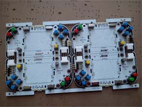
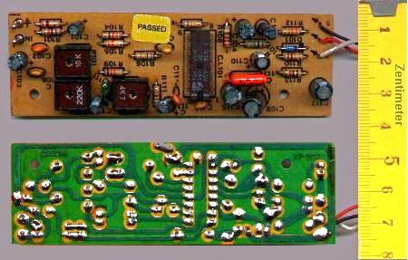
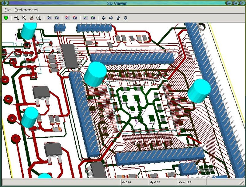
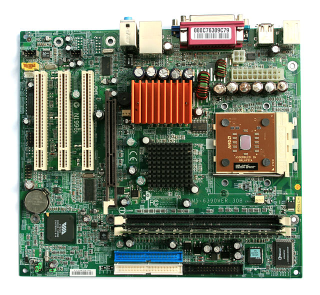
* Solderibility Testing, the samples undergo an accelerated 'aging' process before being tested for solderibility, to take into consideration the natural aging effects of storage prior to board- mounting; In addition to the Engineering Components Inspection we have a higher level of inspection under the customer request.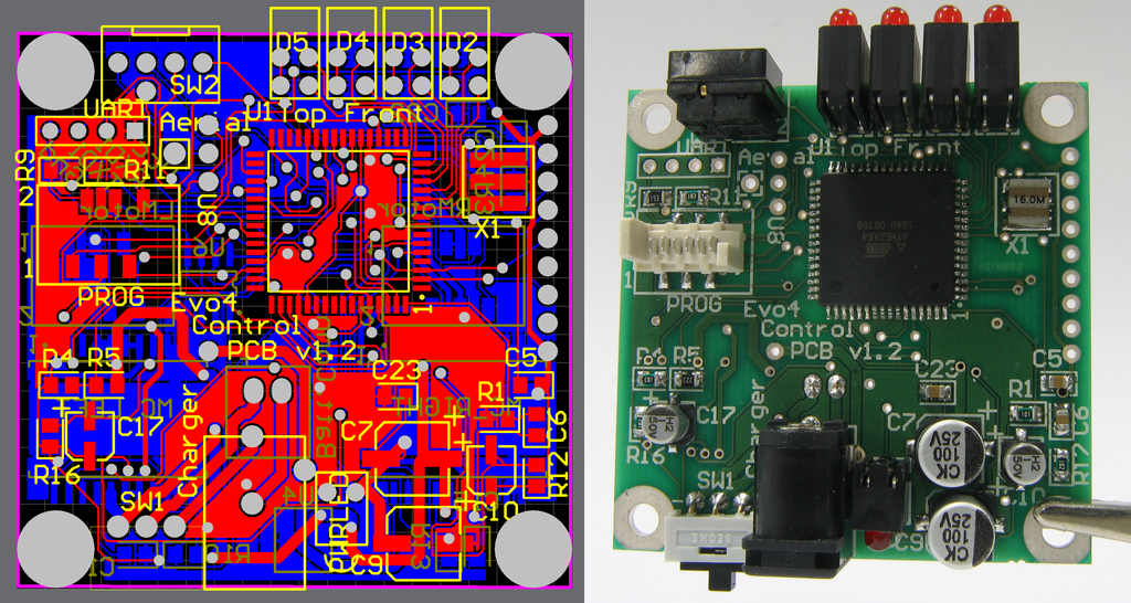 A PCB as a design on a computer (left) and realized as a board assembly populated with components (right). The board is double sided, with through-hole plating, green solder resist and a white legend. Both surface mount and through-hole components have been used.
| Music Porducts |
.jpg) |
| AOI Machine lighting products |
|
| Games Produts |
 |
| Mouser products |
 |
| |
 |
| For THT assembly , the part can be inserted into drill from either top side or bottom side . 3D mosel illustrate it clearly . |
 |
| SMD assembly saves the cost , because it take less time , the parts are only needed to be put on the correct possition ( after the plates are covered with Sn ) , then the PCB to be deliveryed to solder machine . |
 |
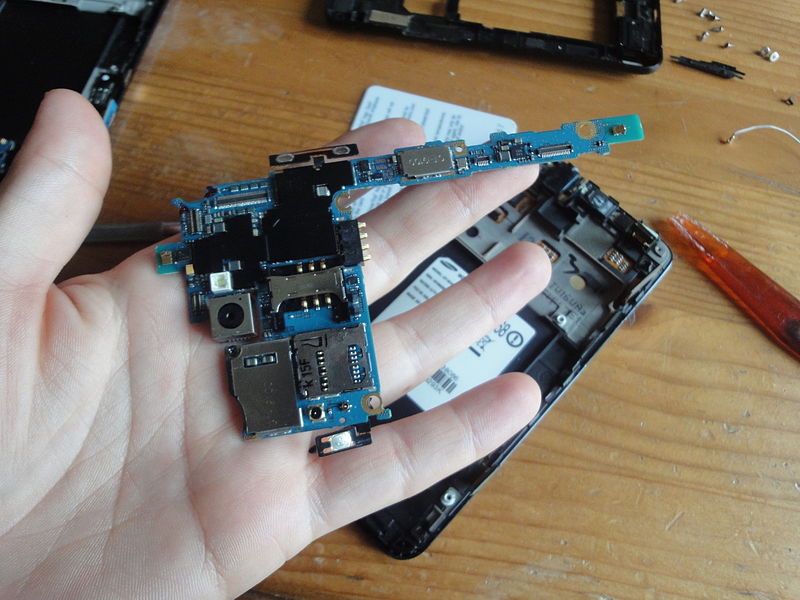
| The motherboard of a Samsung Galaxy SII; almost all functions of the device are integrated into a very small board |
 |
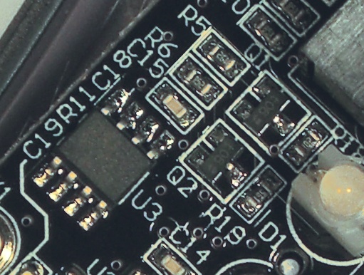
| A motherboard with some faulty capacitors |
 |
| |
|
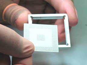
SolderQuik BGA Preforms
Reflow Process
| Ensure all parts are cleaned and baked before reflow |
| 1) Insert Preform |
 |
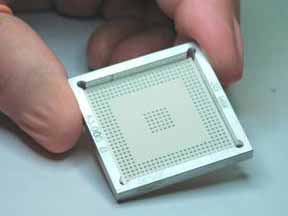
| 2) Check Alignment |
 |
| 3) Apply Paste Flux |
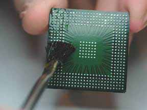 |
| 4) Insert BGA |
 |
| 5) Reflow |
 |
6) Moisten & Remove
Paper |
 |
Why use this service :
Fast
Delivery is typically within 1-2 business days for orders under 200 preforms.
Easy
Learning to use the preform takes less than 10 minutes. Simply flux, apply, and reflow!
Flexibility
Small volume ball attach methods using stencils generally require you to have a different stencil for all of your different array patterns, which gets very expensive.
Winslow Automation currently has a growing database of "standard" array patterns, with new ones being added all the time. We use very flexible tooling to make our preforms. Even if we don't currently have the pattern you need, for a small programming charge we can make nearly any pattern from your drawing .
Adaptability
The SolderQuik BGA Reballing Preforms are designed to work well with the equipment and tools you already have. You can use them with almost any reflow system (convection oven or reflow oven), and they work well alongside most rework stations used for component removal and preparation.
Better Throughput Means Lower Labor Costs
Using stencil methods with either loose solder spheres or solder paste, you can typically process only one component at a time.
Using SolderQuik BGA Reballing Preforms, you can process many parts at the same time with only a few minutes of extra labor. Using preforms, those parts could all just as easily have different pitches, array patterns, and ball diameters.
Proven Technology
Originally developed by Raychem Corporation in 1994, the Solderquik Preform received the SMT Product of the Year Award in 1998. Since then, its low cost, quick turn, east of use & reliability are unmatched.
Technical Specifications
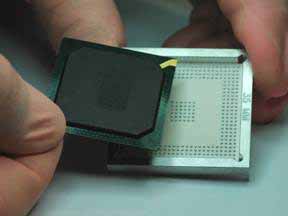
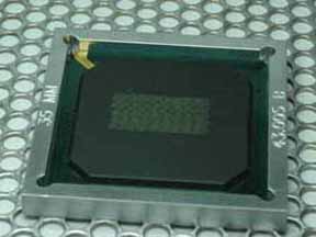
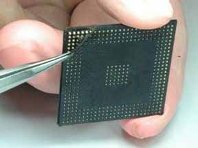
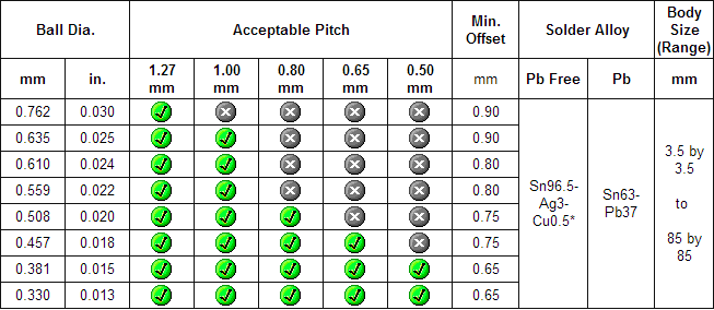 BGA recovery process
Lead-free assembly is available, cost is a little higher than non-lead-free
Environmental Legislation: Historically, Lead Free initiatives were driven by technology and design requirements. Presently, new green board legislation is driving the elimination of Lead in the Printed Circuit Board manufacturing and assembly.Manufacturers and assemblers of printed circuit boards must now take into account: technology, design, environmental, legislative, and final destination when selecting materials for Lead Free products.
The RoHS Directive (Reduction of Hazardous Substances) which involves the banning of certain substances that could end up in land fill sites caused us to re-evaluate our manufacturing strategy with positive results. Our Approach:Throughout the years, we drew up a lead free road map for our assembly facility. Following our extensive investments on ongoing lead free developments, we developed a capable process for both wave soldering and reflow soldering use lead free solders.
This had given us the additional benefit of being one of the first PCB company to offer true lead free enivironment which operate in high temperature environments and those keen to embrace the new legislation and directives early as part of our business plans.
Implentations:In the discussion of Lead Free Assembly, priority is often given to the replacement of Tin/Lead or Solder as the metal finish. However, there are several other elements of the printed circuit board and the assembly process to consider. Laminates can play an important role in successfully converting a process to lead free. Some considerations to keep in mind are:
>>Flame Retardants
>>Higher Tg Material
>>Reflow Temperatures
>>Wave Soldering
Summary:MIER TECH-WISE invests heavily on developing processes which are kinder on the environment.
|